Overview
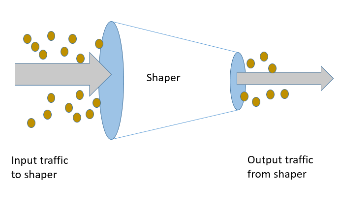
Shaping is a basic and fundamental function in any network. Shaping means control and management of traffic in a network. In IP network, data and information can be sent from one point of network to another points of network using internet framework, which consists of numerous routers, cables, radio resources and many more resources and system to provide the networking framework. There is a capacity limit of each of those resources and system. So we can exchanges a finite amount of data at any given time on this framework. So the manage the amount of data which can be exchanged on a networking framework we need shaping function. This function protects the network from getting overloaded from amount of data. If we imagine network as a pipe and data as a water in a plumbing system, shaping function will make sure the networking pipe is not getting chocked due to amount of data exchanging over it and thus preventing network outage during such overloading scenario.
This was one of the usecase of shaping. In today’s network shaping function is also used to create different business usecases by network operators. It can define business plan using different class of subscriber, like platinum subscriber, gold subscriber, silver subscriber. Each group can have maximum bandwidth limit. Thus based on subscriber plan, the network can cap the subscriber bandwidth limit. Thus a platinum subscriber can get more network bandwidth than gold subscriber and silver subscriber. This business plan can be based on different network application as well. The time critical application like voice call, emergency call, and different other applications critical as defined by local authority and operators can be part of different priority bucket of shaping function, thus to allow basic network function works in time of peak hours, or network congestion. Shaping can be used to share bandwidth fairly to different subscriber, thus preventing some heavy subscriber to hog the network and proving all subscriber the opportunity for basic network function. Shaper function can be defined based on location, like Urban vs Rural limit, taking consideration of population of each location, based on subscriber group like users from University vs Business users, gaming user vs 5G IoT machine to machine users and many more categories.
How does shaper work?
There are mainly two logic for shaping function. One is by adding delay or latency of incoming packet, and another is by dropping packets. Every shaper must have a bandwidth limit or shaper-rate limit. When incoming traffic rate is more than shaper rate limit, but adding extra latency, the outgoing packets can be control to match shaper-rate. This can be done by keeping incoming packet in a queue buffer inside shaper module, till the required packet delay, then transmist the packet to network from shaper buffer,
But shaper can have finite amount of queuing buffer. So if shaper buffer reaches its limit, to maintain shaper rate, incoming packets need to be dropped. In case of TCP flows, when packet drop happens, then TCP end-point can understand the packet of a TCP connection, and thus can slow down the TCP flow rate. The missing TCP segments will be re-transmitted. In case of UDP connection, the application layer needs to take care flow rate and re-transmission logic. Thus in this way shaper can control the rate of the network.
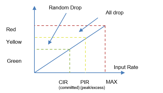
There is 3 colour algorithm for shaper drop logic. Based on shaper rate, the three colour limit are defined inside shaper, i.e. Green, Yellow and Red zone. If the traffic rate is within Green zone limit, there will not be any drop. All traffic will be allowed. This is also called committed information rate or CIR zone. If traffic rate is more than Green zone and bellow Red zone, random packets will be drop. This is because the incoming traffic is going to reach shaper limit. Thus to control shaper rate to cross shaper limit, the early random drop starts. This is called Yellow zone. Different queue management algorithms are used to drop packets randomly, like Codel algorithm, Blue algorithm etc. The limit of Yellow zone is called Peak information rate of PIR. After that limit, no traffic will be allow, i.e. if input traffic is more than Yellow zone, i.e. in Red zone all packets will be dropped.
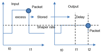
The above diagram shows the pictorial view of how extra latency is added on packet inside shaper module to maintain desired shaper rate. Here without shaping logic, packet would leave the system at t1, but with shaper function, packet leaves the system at t2 , i.e. adding extra latency (t2 – t1) on packet.
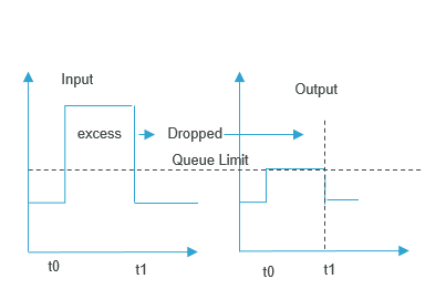
The above diagram is showing shaper rate limit by dropping excess input packets. In network both shaper delay mechanism and shaper drop mechanism logic will work together for shaper function.
